PLUG-IN HYBRID SUVS
By Dean Taylor
From Plug-in HEV news
This note is one of my very occasional notes on what's happening in the world of plug-in HEVs. As I'm an alumni of UC Davis, and proud supporter of the work of Dr. Andrew Frank, most of this note focuses on the prestigious student competition, the USDOE sponsored FutureTruck (held in June 2001) where a plug-in HEV from the University of Calif, Davis took the top prize (see the FutureTruck 2001 Score Summary Sheet on page 7). The UCD fact sheet (see page 6) shows the environmental benefits and other facts of the UCD plug-in hybrid SUV in detail.
A little-known alternative to consumer vehicles currently on the market is the plug-in hybrid electric vehicle. Plug-in HEVs provide much of the benefit of pure electric vehicles (such as significant improvements in energy consumption, lower operating costs, greatly reduced greenhouse gases, and capability of zero tailpipe emissions) while maintaining the long range of conventional vehicles and no-plug hybrids. While providing substantial benefits, plug-in hybrids are expected to have a lower up-front cost than many pure EVs (with mid to long ranges). With the proper incentives, the consumer price for plug-in HEVs may even reach the cost of a comparable "no-plug HEV" or conventional vehicle.
A research group at UC Davis has been building plug-in HEVs for over nine years. Using plug-in HEVs, UC Davis has won four of the nine prestigious USDOE-sponsored advanced vehicle university competitions and recently won the FutureTruck competition with a plug-in hybrid version of a full-size sport utility vehicle. In fact, UC Davis is the only school that builds plug-in HEVs every year.
Sequoia Design Layou
The specification sheet illustrates the performance results and environmental benefits of Sequoia, the winning UC Davis plug-in hybrid SUV. While the truck is a university-built prototype, Sequoia is a well-rounded, fully capable vehicle that is comfortable and maintains all the features of the stock vehicle. It is safe to assume that the results demonstrate the benefits and capabilities of plug-in HEVs in general. For the June 2001 FutureTruck competition, 15 student teams converted a GM Suburban sport-utility vehicle into an HEV. The 35 engineering students at UC Davis won the top prize for best HEV over 14 other universities with "one hand tied behind their back."
Primary Powertrain Design
The emissions, energy use, and CO2 reduction benefits of plug-in HEVs (using EV mode) were dramatically undercounted in FutureTruck. This occurs because the FutureTruck rules assume every trip is a very long trip of 250 miles, rather than using the USDOT data base of real-world behavior (called the NPTS). For example, the mpg equivalent for Sequoia was about 25 mpg at FutureTruck, but when considering a correct mix of HEV and electric modes the mpg equivalent is over 40 mpg! This is excellent performance for a 6,200 pound SUV that provides 60 miles per charge of ZEV range using 29 kWh of batteries.
Unlike many of the other universities, UC Davis did not use a diesel engine (which has less CO2 and energy use). In addition, one competitor created a light weight aluminum frame, which can dramatically boost mpg by saving up to 800 pounds of mass.
FutureTruck rules assume that the round-trip efficiency of batteries is 75%, when in fact Sequoia's battery measures over 92% efficient.
The fact sheet below was put together by UC Davis with test results from the FutureTruck competition at GM's Milford Proving Grounds near Detroit and illustrates environmental benefits based on various methodologies (e.g., based on work by the EPRI-led alliance called the HEV Working Group).
Please when you get a chance, congratulate the UC Davis engineering students and their faculty advisors (Dr. Andy Frank at [email protected]) and (Dr. Mark Duvall at [email protected]).
Articles:
1 Cover Story - Plug-In Hybrid SUVs - Automobile Manufacturers have been backing away from pure battery EVs and embracing HEVs. But until now, all the power still depends on the gas engine (and minor regen) for recharging the batteries. Advances are being made, through University research and competition, to develop and promote plug-in versions of Hybrids. Using the larger SUV platform, here's an in-depth look into how University of California at Davis has been succeeding in this area.
3 The Demise of Zebra/Xebra Motors - What ever happened to the baby-blue EV featured on the TV series Nash Bridges? Her is the chronicled history of the rise and fall of a once-promised EV roadster which, in many ways, has gone the way of the dinosaur.
4 Tire Fitness - Understanding the importance and care of your EV's tire, to keep you rolling smoothly and efficiently.
8 Use an Automatic Transmission in an EV - Most conversions are made with manual transmissions. Here's an approach which allows auto trans to be considered, especially since most of the newer cars come this way.
16 NEVs: A Visit to the Gismo Factory - Michael Everett explores a Neighborhood EV manufacturing facility which produces a compact one-person 3-wheeled car for the masses.
21 Feedback Issues - Explanations provided to the questions EVers are asked, about why charging while driving is not widely considered (free energy anyone?).
30 A Smart Electric in Georgia? - Bob Olham examines how the European Smart car is coming in the electric flavor to the USA.
EVents:
14 The Power of DC - First East-Coast EV drag races. And the winners are....
20 SF Peninsula EAA Rally Pictures - Views of cars and people who participated in the Annual June 2 Tanforan Friendship Rally.
Columns:
10 Shop Talk - Mike Brown's 6th step in the Conversion Workshop - how to install the motor/adaptor/transmission assembly.
12 The Racing Scene - It's all in the photo opportunity.
17 Industry News - The latest in EV-related news.
22 EAA Bylaws - Review of Changes - We need your feedback and comments on modifications and updates to the organizations Bylaws and purpose of the organization. Please look over the changes and respond back with any comments or concerns by October 15.
25 New Board Member - Jerry Asher - The new energy and enthusiasm of a newly appointed director on the EAA Board. Also, call for Elections!
26 EAA Chapter Listings
28 Calendar of Events
29 EV's for Sale
30 EAA Membership Form
31 EAA Merchandise
COVER STORY
Also printed in the Plug-in HEV News, with docs from www.futuretrucks.com
COPYRIGHT 2001 ã Current EVents is a publication of the Electric Auto Association. All rights reserved. While Current EVents and the Electric Auto Association strive for clarity and accuracy, we assume no responsibility for usage of this information. Permission to copy for other than commercial use is given, provided that full credit is given to originator of material copied. This permission does not extend to reprinted articles.
CE STAFF
Publications Committee:
Chairman - Ed Thorpe
Editor - Bob Oldham, Ed Thorpe
Publishers - Ed Thorpe
Assistants - Terry Wilson, Bill Palmer, Scott Leavitt
News in Brief:
Electric Vehicle Today
CE Reporters/Contributors:
John Wayland, Will Byers and others
Photo Credits:
varies, as noted with article
Calendar of Events:
Ed Thorpe
Advertising Manager:
Chuck Hursch
Article Submissions:
The deadline for articles is the first of every month for consideration
in the next issue of CE. Articles received after this date will be retained
for future issues of CE. Contact the Publication Committee for more information.
Advertisements:
A full advertiser's information package and Rate Sheet can be sent by
U.S. Mail, Fax or E-mail. Please contact Advertising Manager or CE Staff
for details.
National EAA: Web Site: www.eaaev.org
By Dave Goldstein
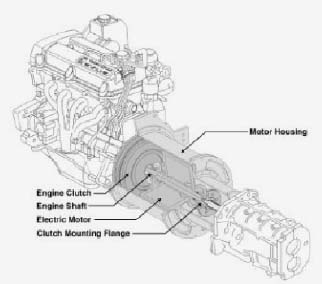
Many may have came across an article about the demise of Xebra Motors. Apparently their assets were auctioned off in June. It has been reported that they built 15 Z3 roadsters, including the Yasmin-Eyes blue one used in Nash Bridges, but nobody seems to know what happened to them. Don Johnson and Darrin Start apparently lost big on this venture.
The full article can be found at http://eastbay.bcentral.com/eastbay/stories /2001/06/18/story8.html
I read the article and in fact, provided background information to author Len Grzanka. It was an interesting and well-written piece, but I would like to clear up a misimpression that some readers may have that either Xebra or its predecessor, Zebra Motors *ever* produced any electric roadsters.
In fact, the "Z3 roadsters" were actually *Tropica* Sports Coupes produced years earlier by Renaissance Cars in Palm Bay, FL, under the guidance of Bob Beaumont, the father of the Sebring-Vanguard CitiCars of the mid 1970's. Zebra simply bought the assets of Renaissance Cars after the original company went belly-up, having failed to secure bridge financing during the height of the anti-ZEV press campaign led by the auto industry. Zebra then *rebadged* the 8 or 10 Tropicas they acquired as "Zebras" and proceeded to sell orders for "new" Zebras that they promised to produce.
Years later, when Zebra failed, having assembled perhaps *2* cars from some leftover Tropica test chassis and spare parts, the assets were sold to "Xebra", which has now failed also.
The cars themselves were quite attractive in mostly white fiberglass, resembling a small Cobra, Miata or BMW Z3 with an integrated roll bar and only a very small wind-screen (like an early Jaguar?). A central battery tunnel held 72 volts of deep-cycle golf cart batteries with a central watering system. A nicely rounded trunk with an integrated center taillight (predating the Porsche Boxster design) held enough space for two golf bags and perhaps an overnight bag.
The all-aluminum chassis featured fully independent suspension, massive side guard beams integrated into the doors and many other safety features (but no air bags.) Top speed, however, was limited by a fixed gear reduction to 65 mph, because Renaissance CEO Beaumont wanted a *roadster* or *runabout* and NOT a "sports car." He was also concerned about the difficulties that a small manufacturer would have in meeting NHTSA safety regulations.
Even so, the car accelerated very nicely, handled beautifully and had excellent brakes. Most private owners modified their Tropicas for even greater speed and performance.
There are varying accounts of the number of Tropicas/Zebras produced. I believe that there were 14 original Tropicas built on the assembly line in Palm Bay, FL. This doesn't including 2 prototypes and at least 2 more rolling test chassis (which may have been later assembled into full cars by Zebra, using spare parts), for a total of 18 vehicles. Some say there were as many as 25. At least 8 Tropicas were delivered to private customers before Renaissance failed. The remaining 10 or so were shipped to Zebra motors in Alameda, CA where the Zebra/Xebra saga began.
I worked as a consultant to Bob Beaumont and Renaissance Cars in those early, heady days in Florida. Bob was subsequently forced out of the company when the Electric Power Research Institute (EPRI) bought in, in a misguided attempt to "rescue" the company. Neither Beaumont nor I had anything to do with the later activities of Renaissance, Zebra or Xebra Motors.
The Tropica/Zebra/Xebra story is far more complicated than could possibly be told in this brief recollection, and will no doubt be the subject of a book someday. The project was initially conceived at a time when Detroit was loudly proclaiming that a roadworthy electric car could not be produced for less than *$125,000*. Ironically, that was about the total cost to produce each Tropica when Renaissance Cars folded, leaving behind more than $2 million in debt from R&D and startup costs.
Behind the scenes, however, there was a brilliant team of "Space Coast" engineers, boat builders and a game plan for cost-effective limited-volume production that predated GM's later Craft Center attempts to build the EV1 in Lansing, MI. And in another irony, Beaumont had chosen GM chassis parts and lined up more than a dozen Florida GM dealerships to sell his car to the public.
In short, the Tropica was a serious contender. Its good looks and thoughtful design were part of its undoing. As costs began to rise and private investments declined, it outlived its designers and became a pawn in the hands of successive groups of investors who admired its style but had no idea what to do with it.
It may also represent the last gasp for small under-funded manufacturers to produce an attractive and affordable roadworthy EV. Today, there are far more stringent NHTSA safety standards for small manufacturers, including expensive air bag requirements and new rules that effectively prohibit the use of inexpensive golf cart batteries. Renaissance Car's initial $2 million investment would not even *begin* to get a car into production in today's business and regulatory climate. And the car that Bob Beaumont once expected to sell as an inexpensive runabout costing less than *$10K* would likely sell for $40K today — IF it could get past the regulatory hurdles and into production in the first place.
I have no idea what became of the powder blue Tropica/Zebra that was painted to match Yasmine Bleeth's eyes, but I do know of at least one other factory original white Tropica — perhaps the last unmodified version left in the country — for sale by private owner for $25K. If anyone is interested and willing to maintain the car in its original condition, please contact me for further information <[email protected]>.
TIRE FITNESS
By Shari Prange, ©1999
When people talk about electric cars, they most often talk about endurance. How long will it run before I have to recharge? It's easy to fixate on the batteries as the most obvious factor in range. However, there are a lot of other, smaller factors that can make a difference. One of them is tires.
Feeling Sluggish?
Tires are the interface between the vehicle and the road. This interface is critical for acceleration, traction, handling, ride smoothness, and rolling resistance. That final item is the one you want to minimize to achieve the best possible range.
Electrical energy from the batteries becomes mechanical energy in the motor, then passes through the transmission and out to the wheels. Rolling resistance refers to anything that sucks away some of that energy from the wheels and diverts it from its useful function in moving the car. Usually, this means energy that is simply wasted as heat. If this waste can be reduced, then more energy is available to turn the wheels and move the car.
Lose Weight & Gain Energy
One way to improve rolling resistance is to decrease the weight load on the tire. This means making the vehicle as light as possible, but it also means making the tires as light as possible.
The weight of the tires may seem trivial in comparison with the rest of the car, especially the battery pack. However, tire weight is rotational weight — it spins. It takes more energy to spin this weight that it would to simply move it in a straight line. Saving ten pounds (4.5 kg) off each tire will have more effect on rolling resistance than saving the same forty pounds (18 kg) in battery weight.
Staying In Shape
Another way to improve rolling resistance is to decrease deflection of the tire. Tires are round, but as they bear down on the pavement, they flatten and the sidewalls bulge. As that portion of the tire rolls up off the pavement, it becomes round again. The tire also deflects even more if it rolls over bumps or potholes. This constant flexing and unflexing causes energy to be wasted as heat.
This is the largest factor in rolling resistance in a tire.
As the tire rolls down the road, it deflects in both the tread and the sidewall. The deflection of the tread is the most critical to rolling resistance. If the tire can be redesigned so that a greater proportion of the deflection occurs in the sidewall and a lesser proportion in the tread, rolling resistance will be reduced.
Substitute Ingredients
Some of the same engineering techniques can be used to reduce both weight and deflection. For example, different materials and construction techniques can make a tire that is both lighter in weight and more rigid.
A tire is not just a big rubber doughnut. There may be as many as a dozen different compounds used in different parts of the tire. The tread will be made from a different compound than the sidewall. Then there will also be multiple materials used in the belts and various reinforcing layers.
In the past, our tires have been steel-belted radials. But in the future, they'll be textile-belted. No, I don't mean hemp cloth. In this use, "textile" refers to well known materials such as polyester and nylon, as well as less familiar strong-but-light materials, such as kevlar and aramid. These materials make the tire both lighter and more rigid.
The rubber is changing, too. Rolling resistance and traction used to be on opposite sides of a scale — if you improved one, you sacrificed the other. Then tire makers discovered that they could substitute silica for some of the carbon black in the rubber compound. This breaks the stalemate. Now you have a compound with low rolling resistance and good traction at the same time.
Building Up
Just as important as the materials used is the way in which they are put together. Some low rolling resistance tires have less tread depth than normal. This might also mean a shorter lifespan for the tire, but it might not, if the tread compound is also adjusted. Other low rolling resistance tires, such as Bridgestone/Firestone, will have the same tread depth as normal tires.
Different manufacturers may focus on different methods to reach the same end. Bart Thompson, tire engineer for Michelin, emphasizes a flatter crown, which is the shape of the top of the tire when seen head-on. Mike Weber, Goodyear tire engineer, stresses a taller sidewall and narrower relative tread.
A final structural issue deals, not with rolling resistance, but noise. Electric cars are quiet, so tire noise is more apparent. In addition to all of the factors we've already talked about, manufacturers have to design their tread patterns to try to minimize road noise.
The challenge manufacturers face is balancing all these factors to get the best total tire package. For example, traction and handling cannot be allowed to fall below acceptable levels in order to achieve low rolling resistance. A tire that deflects less will also give a stiffer ride, so driver comfort becomes an issue.
Lighter materials and thinner sidewalls may mean more susceptibility to sidewall damage. This is less of an issue on a car like the Honda EV Plus, where the tires are fully warranted against road hazards as part of the overall car package. It might be more important on a conversion car without Honda's warranty.
Know Your Limits
Materials and construction are in the hands of the tire manufacturers, but there are things the car owner can control to reduce rolling resistance too.
The tire should be properly matched to the vehicle. It's very important to stay within a tire's rated specs. These are the conditions for which it was designed. Using it outside of these ranges will not yield the best performance, and may actually be unsafe.
Most conversions add several hundred pounds of weight to a car. For this reason, the tires originally specified for that model may no longer be the best choice. You should choose a tire in the correct size that is rated for the car's converted weight.
Ordinary tires, called "Standard Load P-metric" tires, are rated for maximum load
capacity per tire at a standardized 35-psi (pounds per square inch) inflation. Additionally, there are "Extra Load P-metric" tires, primarily available in sizes for light trucks. These tires can carry more weight because they are rated for maximum load capacity at a standardized 41-psi inflation. If your vehicle requires more load capacity than "Standard Load" tires can provide, you should investigate the availability of "Extra Load" tires.
A larger tire (larger in the sense of more air volume) is also capable of carrying more weight. Within the limits of the space available in your wheel well, a larger tire could help carry the extra weight and improve your range as well. If you are running a tire at its maximum load capacity, it will have poorer rolling resistance than a tire run at a fraction of its load capacity. This is because the tire at its load limit will have more deflection. In other words, tires that are rated higher than necessary for your vehicle's weight will give better range performance, all else being equal.
Breathe Deep & Stand Straight
Inflation is very important. A soggy tire will waste a lot of energy. But just how much should you inflate it? Many tires designed for electric cars have been engineered to run at higher than normal inflations. This is part of stiffening the tire. Troy Cottles of Dunlop says the Dunlop DEV-01 issued on the Honda EV Plus is rated for 51 psi. Jorge Pena of Michelin says the Proxima RR is rated for 55-psi.
It is not, however, a good idea to simply take an ordinary tire and run it at a higher inflation pressure. All of a tire's handling characteristics and ability to withstand stress (like hitting potholes) have been engineered for its designated ratings. Once your conversion is completed, it is a good idea to immediately confirm how much weight your vehicle's tires are carrying. Then select a tire size designed to carry that weight, and only use inflation pressures within that tire's specifications.
Higher inflation improves range by reducing tire deflection. In the past few years, many tire manufacturers have begun increasing the maximum allowable inflation on their tires, in the expectation of future
fuel crises. Most of these tires can be inflated as high as 44 psi. This number will be stamped on the sidewall. Running these tires will allow you to use a higher inflation and save energy.
Your inflation needs to be keyed to your car's weight distribution as well. If your car is slightly lighter in the front or rear, reduce the inflation at that end. But don't go below 90 percent of the inflation pressure being used on the heavier end of the vehicle. Also, be sure your car is properly aligned. Bad alignment will wear out your tires unevenly and prematurely, and it will cost you range while it does so.
Same Shoes the Pros Wear
So how do you find a specific tire for your car? For starters, don't even think about using old-fashioned bias ply tires on your electric car. They simply will not stand up to the weight, torque, and handling stresses involved.
You need to look for tires developed for fuel economy on gas cars. Your best bet here is to look for tires that are issued as original equipment on new vehicles, particularly Japanese models. Auto manufacturers push for low rolling resistance tires to improve their Corporate Automotive Fuel Efficiency (CAFE) numbers. This number represents the combined fuel efficiency of their product line, and they are required to meet certain standards with it. The Japanese manufacturers have particularly strict standards for fuel efficiency.
Or Good Cross-Trainers
Conversely, there is very little interest in fuel economy from the public, so tires that are manufactured only for retail sale do not emphasize this feature. Goodyear went to some effort a few years ago to make and promote a low rolling resistance tire. While it was slightly more expensive than a standard tire, the fuel savings over the life of the tire paid for one tire out of four. The public, however, was uninterested.
There are still some low rolling resistance tires out there, though. Michelin's top sellers in this category are the Energy MXV4 and MXV4+. Other fuel efficient Michelin tires are distinguished by the "Green X" on the sidewall. In Dunlop tires, look for models with an "FE" (fuel efficient) or "RR" (rolling resistance) suffix on the model number.
While Goodyear is not promoting any specific models as fuel efficient, there are different models in various sizes that are suitable for electric cars, and have better than average rolling resistance. And Goodyear is offering personal consultation to help you choose your tires. Bill Egan has been a supporter of EVs for many years, and is generous in advising home converters. You can contact Bill at [email protected] for help. Tell him your car model, car weight, and weight distribution fore and aft, and he will give you the product code for the most appropriate tire as well as the optimum inflation pressure to run.
Listen To The Experts
Consumer Reports runs tire tests about once a year. Sometimes they test all weather tires; other times it might be touring or performance tires. However, for any type of tire they include a rolling resistance rating based on their own tests. This is another source of information for your buying decisions.
Another resource is John Rastetter, product information specialist for The Tire Rack, a nationwide business selling tires by mail order. John has many years of experience in the tire industry, and has a great deal of detailed technical information on a wide range of tires. He contributed generously to this article on the subjects of load capacity, tire size, and inflation. You can call him at 1-800-428-8355, extension 347, and he will help you determine the best tire and inflation for your electric vehicle.
Knowledge Is Power
Now that you have all this nifty tire information, how do you use it? First, you need to know what size tires fit on your vehicle, and how much the vehicle weighs. You can often find public scales at landfills, sand and gravel yards, and feed stores. While you're at it, get separate weights for each axle as well. Armed with this info, you can start tire shopping.
Here's where Bill Egan and John Rastetter can be of help, or you can do research on your own. You know how much weight you need to support, and you would like the tire to be rated for even more weight if possible, to improve your rolling resistance. Shop for tires that have the right size and weight ratings.
Next, search among these tire choices for any that indicate they were designed for fuel economy. This might show up as the "Green X" of Michelin, or the "FE" or "RR" suffixes of Dunlop. You can also check the Consumer Reports ratings, and you might find an excellent rating for one of your "dark horse" contenders.
In the end, you might bring it down to a short list of possibilities. Find a knowledgeable tire seller, explain your needs, and let him or her help you make the decision among the final candidates. Just don't be led astray at the last minute by a sales pitch for some other tire unless the salesman can back it up with specifications.
The Holistic Approach
As you can see, there are a lot of factors involved in making a good electric vehicle tire, and these factors interact with each other in sometimes complex ways. What this means to you is that there is a lot more to buying tires than finding the best price, or even the best warranty. If you want to get the best performance from your electric car, you should think of the tires as an integral and important part of the overall system. In the long run, the best match of tires to vehicle will be the best bargain. Shari Prange, Electro Automotive, PO Box 1113-HP, Felton, CA 95018-1113 * 831-429-1989 * [email protected] * www.electroauto.com
Bill Egan, Goodyear Tire & Rubber Company, PO Box 3531, Akron, OH 44309 * 330-796-2715 * Fax: 330-796-2715 * [email protected] * www.goodyear.com
John Rastetter, The Tire Rack, 771 West Chippewa Ave., South Bend, IN 46614 * 800-428-8355, 219-287-2345, extension 347 * Fax: 219-236-7707 * [email protected] * www.tirerack.com
This article also appeared in Home Power magazine.
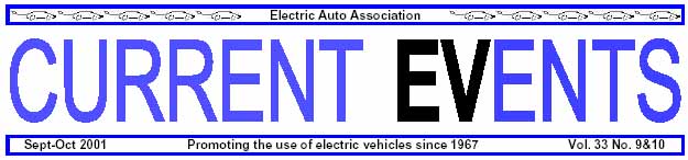
Sequoia is a 2000 Chevrolet Suburban modified to operate as a hybrid-electric vehicle. The truck uses a "plug-in" control strategy that maximizes all-electric operation in urban and freeway driving; the battery is recharged from the grid electric supply. The engine is used occasionally for long trips (to sustain the battery charge when the battery becomes partially depleted) and for additional power during towing or maximum acceleration. The stock Suburban features a 5.3L V8 engine, four-wheel drive, and an automatic transmission and has a curb mass of 2523 kg.
Vehicle Specifications
Vehicle Curb Mass 2807 kg, including fluids
Engine
Manufacturer / Type: General Motors (Saturn) / 1.9 liter Inline 4-cylinder,
Dual Overhead Cam
Maximum Power: 95 kW @ 5600 rpm
Maximum Torque: 158 N-m @ 4800 rpm
Fuel System: Sequential Electronic Fuel Injection
Emissions System: Close-Coupled Catalyst; Hydrocarbon Trap;
Electrically Heated Three-Way Catalyst; Air Injection
Throttle Control: UC Davis drive-by-wire
Transmission
Primary (rear wheels) Secondary (front wheels)
Manufacturer: Richmond Gear Bay City Iron Works/Richmond Gear
Type: 6-speed manual single speed
Gear Ratio: 4.41, 2.45, 1.57, 1.24, 1.00, 0.81 2.5
Final Drive Ratio: 4.56 (General Motors) 3.73 (General Motors)
Electric Motors
Primary (rear wheels) Secondary (front wheels)
Manufacturer: Unique Mobility Precision Magnetic Bearing Systems
Type: DC Brushless w/regen brk'g DC Brushless w/regen brk'g
Maximum Power: 75 kW @ 3500 rpm 75 kW @ 3500 rpm
Maximum Torque: 240 NM @ 0 rpm 239 NM @ 0 rpm
Energy Storage
Manufacturer / Type: Ovonic Battery Company / Sealed Nickel-Metal Hydride
Capacity: 29.0 kWh (@ C/3)
Peak Power: 185 kW (@ 50% DOD)
Mass: 441 kg
Fuel Type: Reformulated Gasoline
Capacity: 15 gallons
Battery Charger
Manufacturer / Type: General Motors "MagneCharge" / Inductive
Output Power: 6.6 kW
Input Voltage: 220 V AC
Control System
Software: All UC Davis designed
Hardware: UC Davis designed, except PCM microcontroller (Microsys)
Data Communication: CAN Bus
Accessories
Air Conditioning: Electric (Sanden)
Power Steering: Electric (Delphi)
Telematics: Advanced Vehicle Information System with rear-view camera,
powertrain status feedback and wireless interface; audio-video entertainment
system with three independent displays and wireless interface to household
network
FutureTruck 2001 Results
Sequoia GM Suburban (units)
Energy Economy 1 City Hwy City Hwy
All-electric (EV) 367 403 N/A N/A DC Wh/mi
Charge-sustaining (HEV) 23.6 27.2 N/A N/A mpg
Combined driving 2
Consumer perspective 3 49.3 48.7 15.6 20.5 mpeg
Societal perspective 4 4,384 4,496 8,910 6,760 Btu/MI
Petroleum use 5 84% less 80% less baseline baseline
Refueling Cost
All-electric (EV) 2.8 N/A cents/mile
Charge-sustaining (HEV) 6.6 N/A cents/mile
Combined driving 3.7 9.5 cents/mile
Range City Hwy City Hwy
All-electric (EV) 7 64 59 N/A N/A miles
Charge-sustaining (HEV) 355 408 N/A N/A miles
Total, typical driving 460 560 miles
Tailpipe Emissions
All-electric (EV) California ZEV N/A
Charge-sustaining (HEV) California ULEV N/Z
Combined driving below California SULEV 8 California LEV
Greenhouse Gas Impact 9 GHGI Reduction GHGI
FutureTruck calculation 10 432 48% 828 grams/mile
FutureTruck corrected 11 413 50% 828 grams/mile
NPTS/Nationwide 2010 12 273 67% 828 grams/mile
NPTS/California long-term 13 213 74% 828 grams/mile
Acceleration
0-60 mph time 8.9 8.9 seconds
Time to ¼ mile 17.7 14 17.3 seconds
Trailer Towing (estimated)
Charge-sustainable speed with 7000-lb trailer
0% average grade: 65 N/A mph
2% average grade: 60 N/A mph
7.2% average grade: 35 N/A mph
Top speed with 7000-LB trailer
0% grade: 80+ 80+ mph
2% grade: 80+ 80+ mph
7.2% grade: 65 65 mph
Notes
1. Energy Economy figures are uncorrected results of dynamometer testing on the FUDS (city) and FHDS (highway) federal driving cycles.
2. "Combined driving" represents a weighted average of EV and HEV modes based on Sequoia's all-electric capability. The percentage of all-electric operation is derived from driving statistics in the 1995 US. Department of Transportation Nationwide Personal Transportation Survey (NPTS), and assumes the vehicle is recharged every night. For a vehicle with 60 miles of all-electric range per charge, the NPTS statistics indicate that EV mode can be utilized for 74% of total driving miles.
3. Represents the refueling energy supplied to the vehicle by the consumer. The amount of electric recharging energy drawn from the consumer's wall plug is converted to an equivalent amount of gasoline and added to actual gasoline consumed to obtain an equivalent gas mileage ("mpegg" = miles per equivalent gasoline gallon). Battery and charger losses have been applied to the electricity usage. Note that mpegg values increase dramatically with increasing all-electric operation; the equivalent fuel economy of Sequoia during all-electric operation is 75.0 mpegg on the city cycle.
4. All "upstream" energy (including refining, transportation, and power plants) has been included in order to calculate the total "well-to-wheels" energy consumption on a national basis. The amount of upstream energy is calculated using Argonne National Laboratory's Greenhouse Gases, Regulated Emissions, and Energy Use in Transportation (GREET) Model, Version 1.5a. Electricity production is based on the nationwide generation mix forecasted for 2005. Due to higher electricity production efficiency, Sequoia's upstream energy use in California would be approximately 12% less.
5. Sequoia's all-electric capability permits a reduction in petroleum use of approximately 75%; the remainder of the reduction is due to improved gasoline fuel economy.
6. The gasoline price is assumed to be $1.65/gallon, a national average; the electricity price is assumed to be $0.06/kWh, a weighted average of on-peak and off-peak electricity rates available to electric vehicle users (source: "Comparing the Benefits and Impacts of Hybrid Electric Vehicle Options," Electric Power Research Institute). Note that the gasoline price in California is currently approximately $1.80/gallon, and the off-peak electricity rates of some California utilities have recently increased to about $0.08/kWh (July 2001).
7. Battery discharged to 80% depth-of-discharge
8. Sequoia's average emissions are approximately 50% less than the SULEV standard, assuming nightly charging and combined driving based on NPTS statistics.
9. The Greenhouse Gas Impact (GHGI) represents the CO2 equivalent of tailpipe and upstream CO2, CH4 and N2O emissions.
10. The FutureTruck method assumes that all trips are 250 miles in length. For Sequoia, such a trip construction assumes that approximately 25% of all driving miles utilize EV mode while 75% of miles are driven in HEV mode. This calculation does not correlate with NPTS statistics.
11. Adjusted for Sequoia's correct battery efficiency.
12. Assumes trip length statistics from the National Personal Transportation Study and nightly charging. Uses greenhouse gas emissions of national-average electricity generation in 2010, assuming incremental use of power plants during off-peak hours (source: "Comparing the Benefits and Impacts of Hybrid Electric Vehicle Options," Electric Power Research Institute). The greenhouse gas emissions of current California average electricity generation are slightly less than this forecast of 2010 national-average emissions.
13. Uses greenhouse gas emissions based on a Department of Energy/Energy Information Administration 2015 forecast of the average electricity generation mix in California.
14. Sequoia's electric drive system was not fully functional during this test. The ¼-mile time will be faster with full system operation.
HEV Update
P.S. For those of you who don't follow plug-in HEVs, there has been a recent ground swell of interest.
In North America, the HEV Working Group is releasing their Phase 1 comparison of mid-size HEVs (with and without a plug) in early August. This two-year, $2 million effort led by EPRI involved automakers, utilities, research institutions, and federal/state/local government and looked at performance, energy use, environmental benefits, technological issues, costs, existing incentives, and consumer interest. The results are exciting and will soon be posted at www.epri.com.
In addition, there are over 20 plug-in HEV buses in Italy (by Autodromo) and Toyota's subsidiary Hino has a shuttle, a full-size transit bus, a full-size touring bus, and a delivery van. Additional HEVs around the world are the commercial plug-in HEV forklifts in Europe (by Linde and others) and plug-in HEVs in Japan by Toyota. And Renault is releasing the world's first commercial light duty plug-in HEV — a "microvan" called the Kangoo in four European countries in early 2002.
Finally, EVAA is working on a plug-in HEV amendment to the tax credit provisions of the CLEAR ACT (by Senators Hatch, Rockefeller, Jeffords) so that the larger environmental benefits of plug-in HEVs (compared to no-plug HEVs) will be rewarded with a larger tax credit.
(For more information on the tax credit amendment, go to "www.evaa.org" then go to government activities and then to legislative action center and enter your ZIP code.)
by Will Byars, with editing by Bob Oldham
You can use an automatic transmission in a late model electric vehicle conversion; you just need to put a little more thought into it and get a few different pieces made. By far the easiest transmissions to use are the variants of the TH350, TH400, TH700R4, TF727, C4, C6 and other such long-lived designs from rear wheel drive platforms of the big three. Why? Their new versions, the electronically controlled ones, share the same bolt patterns and mounting provisions of the old ones! For example, a 4L80E (Chevy) is just a newer version of the old TH400 transmission. There are also a few front-wheel-drive transmissions that are variants of the rear-wheel-drive transmissions that preceded them. You have a few options: hack the computer to make it do what you want (custom chip), use an aftermarket shift controller with a custom chip, or replace the computerized transmission with a non-computerized version. It's possible that aftermarket hot-rod parts meant that for the rear wheel drive version of the same transmission would fit, giving you the option of manually controlling the shift points.
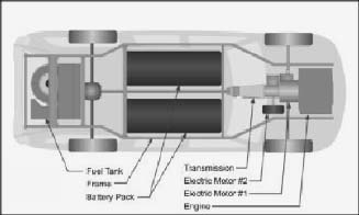
To run an automatic most efficiently in an EV, you need to remove its worst part: the torque converter. You can potentially hack it up and get the various splined coupling bits off of it and use them to make your connection from motor to transmission. Here's where you make your next choice: internal pump or external pump? Run the internal pump with the traction motor or with a separate motor?
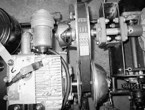
thing whenever the engine is running. Inside the torque converter is a rotor that is spun by the fluid pushed by the spinning outer case. The transmission input has two concentric shafts; the outer torque converter casing is connected to the outer splined input shaft of the transmission, which turns the pump in the transmission that supplies the hydraulic pressure to operate the various systems in the transmission. The inner part of the torque converter, the "driven shaft" in the picture, is connected to the inner input shaft of the transmission, which is what supplies the torque that passes through the gears, bands, clutches etc. inside the transmission.
If you want to use an external pump, you have to rip out the existing pump and re-route some internal passages to allow the input of pressurized hydraulic fluid from your external pump and to allow access to the transmission sump to get it back to the pump. If you want to use the internal pump and drive it with a separate motor than the main drive motor, use the two splined connectors you cut out of the torque converter to make two separate connectors. One of the connectors with a pulley on it to drive the pump, and one with a solid connector to connect the traction motor to the torque input shaft. If you want to run the internal pump from the idling traction motor, just connect both splined bits to the same direct coupler from motor to transmission. However, this means that when the vehicle is stopped the traction motor must run at an "idle" speed to keep hydraulic pressure up _ a finicky adjustment on the controller side of the equation.
The factors that go into how you want to do it are complexity, weight, cost, and efficiency. Bigger motors are more efficient, but possibly not at low power outputs. For what it's worth, since you have to re-program the transmission anyway, it may be easier to just run everything off the traction motor. Put a pulley on the other end of the motor or build it into your coupler to run the power steering pump, the A/C, and whatever else you want to provide rotary power to when the car is "on" and in "drive". (This will of course necessitate a governor to maintain motor speed with changing loads.) If you pick the right power steering system (one compatible with regular ATF) you can run
the power steering off the pump inside the transmission. This can eliminate one extra motor and pump, at the expense of needing some more high-pressure lines and adding another return to the automatic transmission sump, plus most likely an additional oil cooler to keep the ATF happy. For those with heavier vehicles, there is available a "Hydroboost" brake booster system (in many larger diesel vehicles, like GM and Dodge and Ford pickups) that runs off the power steering system. If it is also compatible with the ATF, there goes the vacuum pump as well! If the transmission pump can't "keep up" with that entire load, you can add a hydraulic accumulator and/or buy an aftermarket higher-volume pump. These are available from the heavy-duty version of the transmission and/or racing parts suppliers, if available at all for that transmission. Do your homework! :-) An alternative method might be to combine the auxiliary functions above _ brake boost, power steering — into one hydraulic system with accumulator and run a separate motorized hydraulic pump with a pressure switch. Alternatively, you can add a solenoid-controlled hydraulic accumulator that "charges" while driving and will "dump" a slug of pressurized ATF to the transmission when you want to start moving. Adding a pressure switch somewhere in the hydraulic circuit in the transmission would allow delaying power input to the traction motor until the transmission has sufficient pressure to operate.
Next up is reprogramming the transmission. You need to modify the programming either electronically or mechanically depending on your application. Basically, you want the transmission in a lower gear for acceleration and a higher gear (but not TOO high) for cruising. If a custom chip or transmission controller is available for your transmission then it is possible that you can get the supplier to burn you one with the parameters you want for a nominal fee over the regular cost, or possibly free if they are enthused by the idea! :-) For mechanical reprogramming, you can get "shift kits" that firm up the shifting and raise the shift points for the transmission. Then you "reverse the sense" of the "kickdown" mechanism to "kick up" instead, causing the transmission to run in low or 2nd gear normally and shift up to high for acceleration, etc. For a number of transmissions, you can get a fully
You can use an automatic transmission in a late model electric vehicle conversion; you just need to put a little more thought into it and get a few different pieces made. By far the easiest transmissions to use are the variants of the TH350, TH400, TH700R4, TF727, C4, C6 and other such long-lived designs from rear wheel drive platforms of the big three. Why? Their new versions, the electronically controlled ones, share the same bolt patterns and mounting provisions of the old ones! For example, a 4L80E (Chevy) is just a newer version of the old TH400 transmission. There are also a few front-wheel-drive transmissions that are variants of the rear-wheel-drive transmissions that preceded them. You have a few options: hack the computer to make it do what you want (custom chip), use an aftermarket shift controller with a custom chip, or replace the computerized transmission with a non-computerized version. It's possible that aftermarket hotrod parts meant that for the rear wheel drive version of the same transmission would fit, giving you the option of manually controlling the shift points.
To run an automatic most efficiently in an EV, you need to remove its worst part: the torque converter. You can potentially hack it up and get the various splined coupling bits off of it and use them to make your connection from motor to transmission. Here's where you make your next choice: internal pump or external pump? Run the internal pump with the traction motor or with a separate motor?
The "drive shaft", or input shaft, is normally hooked to the engine. The engine driveshaft is connected solidly to the outer case of the torque converter, and, hence, spins the whole manual valve body, which allows you to shift it without a clutch any time you want.
There are internal friction clutches and bands that do the de-coupling and coupling for you, and with racing parts there is no need to drop power to the traction motor during shifting, though it may be desirable for "smoothing" the shifting. If you are running an external or externally driven internal pump, you're done.
If you run the internal pump off the traction motor, you have one more thing to do. You need to add something akin to a "clutch pedal" circuit. Basically, you find the hydraulic actuator that connects input torque to first gear and rig it so that it drops pressure to that band and/or clutch when the vehicle gets below a certain speed and/or when a switch or pedal is depressed. Probably the simplest arrangement would be a microswitch on the potbox that disconnects the torque whenever the "throttle pedal" is not pressed. The actual details of how to do the hydraulic connections will have to be figured out by whomever are doing the converting.
Ditching the torque converter cuts the losses of an automatic transmission significantly, and "firming up" the shifts, as with a racing-style shift kit, also cuts the losses by reducing the "slip" in the bands and clutches during shifting. Both also dramatically cut the heat added to the fluid, making it run cooler and last longer. Planetary gearsets are possibly more efficient than the gears found in a manual transmission as well, and ATF is a much lower viscosity fluid, which further reduces drivetrain drag.
Lastly, you can add to the programming/switching/controlling/ design, such that power input to the traction motor is locked out whenever the transmission is shifted to neutral or park, greatly alleviating the danger of runaway on a series-wound motor.
Done right, this could make for a very pleasing and easy to drive vehicle. For long-established transmission designs there are even a number of different gear ratio combinations available in either different vehicle models or from aftermarket sources, allowing you to "tune" the transmission to your particular motor/controller/vehicle combination. Some cars even have 5 and 6 speed automatic transmissions available, making a more efficient match between motor speed and vehicle speed possible.
It is also worth mentioning that several of the newer automatic transmissions use an electric solenoid valve to control the flow of pressurized hydraulic fluid in the transmission. Armed with a schematic, an exploded diagram of the transmission and a hydraulic circuit diagram it should be relatively easy for someone to devise an adjustable shift controller for the transmission to replace the interface with the vehicle's main computer. With a little more work, one could potentially build a replacement computer module that would fit in place of the donor vehicle's computer and allow use of a number of existing circuits in the ICE wiring harness for EV purposes. This would allow a very seamless integration between the electric components and the vehicle.
CONVERSION WORKSHOP, STEP 6
INSTALLING THE MOTOR/ADAPTOR/TRANSMISSION ASSEMBLY
By Michael P. Brown, ©2001
In the last issue, we talked about the types of motors and adapters available. In this article we will discuss installing the adaptor on the motor, joining the motor/adaptor assembly to the transmission, and finally, the installation of electric drive system in the car or truck. Note: The adaptor installation procedure is for the adaptor system I sell. Other suppliers have different procedures. Follow the instructions that come with your adaptor.
Motor Handling
Since the motors we are installing weigh from 100 to 150 pounds, they should be handled with care to avoid damage to the motor or yourself. It isn't easy to pick up a heavy motor with smooth sides and no big projections to get a grip on, To make it easier, thread two 3" bolts of the right thread size in two of the mounting holes opposite each other on the drive end of the motor. If you have an Advanced DC motor, you can do the same thing on the brush end because mount holes are provided at that end, too.
Be sure to thread the bolts all the way into the holes to avoid damage to the threads. If you have a Prestolite or GE motor, removing the brush cover and holding on to the motor through the brush access holes in the end bell is about your best bet.
The Advanced DC motors have a hole in the side of the motor tapped 5/8"-11 for an eye bolt used for handling the motor during the manufacturing process. If you decide to use this method to move the motor around, be very careful to thread the bolt in finger tight only, and lock it in place with a lock nut placed on the bolt before it is threaded into the hole in the motor. The reason for this is that the bottom of the hole is one of the field coil shoes and trying to tighten a bolt against it will force it into the armature and damage the motor.
Bench Work
Now that we can pick the motor up and move it around safely, let's talk about where we
are going to put it and how we are going to keep it there. The usual destination is a workbench or freestanding worktable, but once the motor is there, it needs to be held in place so it can be worked on without moving around and possibly falling off the bench.
The way I do this involves two 3/8" holes I have drilled into the top of my work bench about 20" from each other. The motor is placed between the holes. Two 3/8" eyebolts are inserted in the holes and held in place with nuts threaded on from under the bench top. Next, a piece of 5/16" chain is hooked to one eyebolt and passed over the motor toward the other eyebolt (with some padding, such as rags, foam rubber, or cardboard between the chain and the motor to prevent damage to the motor).
Then a threaded turnbuckle, with its ends extended to almost their maximum length, is fastened between the end of the chain and the remaining eyebolt. When the turnbuckle is tightened, it gets shorter and the chain pulls the motor tightly to the bench.
If you don't want to drill holes in the top of your workbench, get a piece of 2"x6" wood plank about 36" long, drill the holes, and install two "T" nuts into the holes from what will be the bottom of the board. This gives metal threads in the wood plank to screw the eyebolts into. Put lock nuts and flat washers on the eyebolts before threading them into the "T" nuts. Put this holddown board on the top of your workbench and fasten the motor to it instead of the bench.
Which Way Is Up?
The reason for holding the motor so firmly to the workbench is to keep it from moving around while we are installing the adaptor. But before we cinch it down, we need to make sure everything is pointing in the right direction. It is critical that the motor terminals are oriented in a position relative to the top edge of the transmission bellhousing that allows them to be accessed for service. At the same time, you want to be sure they aren't interfering with things like battery racks, drive axles, or frame crossmembers.
When this orientation has been determined, place the motor on the work bench or holddown board with the terminals pointing in the desired direction, and tighten the turnbuckle. This system will keep the motor in one place on the bench, but it will not keep it from rotating when the fasteners holding parts of the adaptor to the motor are tightened.
I use a metal bar with a hole in one end as an anti-rotation bar. The bar is fastened to the brush end bell of the motor with a bolt through the hole in the bar and threaded into one of the mount holes on the motor. The other end of the bar is pointed toward the right side of the motor, and under another bolt threaded into one of the other mount holes in the end bell. The free end of the bar rests on the bench top which keeps the motor from rotating by forcing the bar against the second bolt.
It might be necessary to rotate the motor a little to achieve this, which is OK. However, if there is more than one inch between the end of the bar and the bench top when the bar is against the stop bolt, use a block of wood to make up the distance.
Adaptor Installation
Note: The following instructions describe the installation of an adaptor on an Advanced DC motor. However, adapter installation on other brands of motors is a similar sequence of events.
The ¼" square key provided in the adaptor kit is the first part installed. Since it is a loose press fit in the key slot of the motor shaft, it is gently tapped into place with a brass hammer until it is fully seated and the end of the key is even with the end of the motor shaft. Temporarily install the tapered bushing over the shaft, and key to check that it slides along the shaft freely. If it doesn't, check that the key is seated properly and that there are no burrs on the key or shaft. Free back and forth movement of the bushing on the shaft will be important very soon.
Next, the motor ring is fitted over the locating projection on the motor face, and bolted to the motor with the four 3/8"-16 socket head cap screws provided in the adaptor kit. Place a drop of red Loctite thread locker on the bolt's threads before installation. Tighten all the bolts firmly, then torque them to 35 ft/lbs.
With the motor ring in place, the next part to install is the profile plate. The profile plate has a locating recess on its motor side that fits over a locating projection on the motor ring. Place the plate on the ring, with the top of the plate in the position it needs to be in relative to the motor lugs. Secure the plate to the ring using Loctite as above on the bolts, tighten the bolts firmly, and torque them to 35 ft/lbs.
Two types of bolts are used here, depending on the amount of room between the back of the flywheel and the profile plate. If there is a lot of room, a regular ½"-13 hex head bolt with a ½" flat washer is used. If clearances are tight, a ½"-13 flat head bolt is used. The correct bolts for the adaptor are provided in the kit.
Installing the adaptor hub and bushing assembly is the most critical part of the process. First, we slide the bushing on the motor shaft, with the large diameter end facing the motor. Next, slip the hub over the bushing, and align the counterbored holes in the center of the hub with the threaded holes in the bushing. Thread the 10-24 cap screws, included with the adaptor kit, through the hub and into the bushing. Tighten the cap screws gradually in a criss-cross pattern, drawing the bushing into the hub until you start to feel resistance when sliding the hub back and forth on the motor shaft.
At this point, tighten the screws a little bit more until it takes an effort to move the hub along the shaft. Now place the flywheel on the hub and temporarily bolt it to the hub using two of the original flywheel bolts. Tighten the bolts hand tight.
With the flywheel in place, we can duplicate the "magic distance": the measurement we took when the flywheel was still bolted to the IC engine. Slide the flywheel/hub assembly along the shaft until the distance from rearmost flat surface of the flywheel to the profile plate is your "magic distance", plus .020" to allow for pull-in when the cap screws are fully tightened.
Now, if the cap screws are still visible, tighten them snugly. Note: Do not over tighten the cap screws, as they will break. The taper action between the hub and bushing is where the holding power is. The cap screws just set that taper action in place. Recheck the "magic distance", and it should be whatever your distance was, plus or minus .010".
If the flywheel covers the cap screws after you have set the "magic distance" plus .020", gently remove the flywheel, tighten the cap screws, reinstall the flywheel, and recheck the "magic distance". If you miss the "magic distance" even within the plus or minus .010" tolerance, just loosen all the cap screws until they stick out above the face of the hub, hit them sharply with a brass hammer to break the taper, and start over. If the capscrews don't stick out far enough, or you are nervous about hammering on them, buy two 10-24 capscrews ¼" to ½" longer than the ones that came with the adaptor kit and tap them with the hammer instead.
Flywheel and Clutch Installation
After the hub and bushing are locked in place with the "magic distance" set, we can permanently install the flywheel. Now is the time to have the flywheel's friction area resurfaced, starter ring gear removed, and have the flywheel lightened if you think it's necessary.
I do not recommend flywheel lightening being done by anybody other than an automotive machine shop that does high performance engines and knows where to take the weight off safely. This kind of shop would also have ability and machinery necessary to re-balance the flywheel after lightening. If you are having the flywheel balanced, give the shop the new clutch pressure plate you are going to install, and have them balanced as a unit.
Before installing the flywheel, check to see if there is a pilot bearing or bushing that needs to be lubricated or replaced. Since this small but critical part is in the very center of the drive system, now is the time to pay some attention to it.
Some pilot bearings are sealed permanently lubricated ball bearings that are installed in the hub or flywheel. Replace this type of bearing with a new one. Another type of pilot bearing is a caged roller bearing with the rollers exposed in the center of the bearing where the pilot shaft runs. This type of bearing is usually installed in the hub. I install a new bearing in the hub as part of the kit when this type of pilot bearing is used.
The pilot bushing is usually made of a brass or bronze alloy and is pressed into the hub. It is a very simple part that has been in use since the dawn of the automotive age. My machinist makes our pilot bushings to suit when they are called for, and they come pressed into the hub as part of the kit. Both the caged roller bearing and the pilot bushing need to be lubed prior to use. A sparing amount of molybdenum based grease (moly grease) packed between the rollers or coated on the inside of the bushing is usually enough for the life of the clutch. Too much grease might find its way onto the clutch disc causing slippage.
Install the flywheel, using the original bolts and lockplate if one was used (check your factory service manual to see if they specify the use of new bolts or lockplate). Use a flywheel lock to prevent rotation, and torque the flywheel bolts, using the crisscross tightening pattern, to the torque given in the factory service manual.
Flywheel locks are tools that prevent the flywheel from turning when the flywheel or clutch bolts are being tightened and torqued. They usually work by being inserted between the moveable flywheel ring gear teeth and immobile bolt on the adaptor plate. Some can be purchased quite cheaply while others can be fabricated by the user much more economically. Go to a repair shop that works on your donor's make of car, and see what they use to get some idea of what you have to build. If you had the ring gear knocked off the flywheel, you will have to get more creative in your flywheel lock design.
Now we are ready to install the NEW clutch. Note the emphasis on the word new. It not an economical idea to install used clutch parts, or even new parts of questionable quality, in the center of a drive system that is buried under several hundred pounds of batteries. Buy new brand name parts, install them correctly, and you won't have to worry about them for many thousands of miles.
Use a clutch pilot tool to center the clutch disc on the flywheel. The clutch pilot tool is a short shaft that mimics the transmission main shaft. It has splines that match the splines on the inside of the clutch disc hub, and has a diameter on one end that fits into the pilot bearing. This tool makes sure that the clutch disc hub is concentric with the centerline of the motor shaft. Inexpensive plastic clutch pilots are available for almost all makes of cars and trucks at the parts house where you buy the rest of the clutch parts.
Install the new pressure plate over the pilot tool and centered clutch disc. Line up the locating holes on the plate with the locating pins on the flywheel. If you had the pressure plate and flywheel balanced as an assembly, line up the locating marks for the balance point at the same time. Slide the plate over the pins as far as it will go. Thread the original pressure plate bolts into the holes in the flywheel and tighten them finger tight.
Reinstall the flywheel lock, and tighten the bolts in a crisscross pattern an equal number of times for each bolt in several passes until the bolts are snug. This method keeps the pressure plate from being warped as the clutch springs are compressed when the plate is being pulled down to the surface of the flywheel. Finally, torque the bolts to their specified torque and remove the flywheel lock and clutch pilot.
Install a new throwout bearing (a.k.a. clutch release bearing) in the transmission bell housing. Be sure and lube any sliding surfaces between the bearing and operating arm, or bearing and guide tube, with moly grease. Your service manual will show these lube points.
Joining the Motor/Adaptor Assembly to the Transmission
This operation gets a little tricky, as we are joining a fairly heavy motor and adaptor assembly to a transmission or transaxle that weighs almost as much. The best way to do this is to use the engine hoist you have rented or borrowed to pick the assembly off the bench. Use the engine sling that came with the hoist, with one end fastened to one of the mount holes on the front of the motor, and other end to one of the adaptor-to-transmission bolt holes in the profile plate.
Lower the motor and adaptor down onto some wood blocks that are thick enough to hold them off the ground with a few inches under the bottom of the profile plate. Remove the bolt holding the end of the engine sling to the profile plate. Prepare the transmission by applying a small amount of white grease to the clutch splines. Don't overdo this, as too much grease could damage the clutch disc in operation. Also at this time, tap the locating dowels into their holes in the transmission.
By now you should have selected the fasteners you are going to use to fasten the transmission to the adaptor. Put them within easy reach of the motor. Next, round up two assistants, one to steady the motor/adaptor assembly, and another to help you lift and position the transmission.
Pick up the transmission and carry it to the motor assembly. Insert the mainshaft into the clutch hub and wiggle it around a little until the splines on the clutch hub and the mainshaft line up, and the transmission starts to move toward the adaptor. Line the dowels in the transmission up with the corresponding holes in the adaptor plate, and continue pushing the transmission in until the mating surfaces touch.
Bolt the two joined pieces together with the selected fasteners and block up the transmission to keep it from tipping the assembly over. Install as many of the joining fasteners as you can reach, and reattach the end of the engine sling previously removed.
Re-hook the sling to the engine hoist and lift the motor and transmission unit off the blocks. Install any previously unreachable fasteners. Before we install the drive system in the car or truck we should check the transmission mounts for damage or wear and replace them as necessary.
Installing the Motor & Transmission in the Vehicle
Installing the new drive system is the reverse of the procedure used to remove the old IC engine and transmission. However, this is not yet the time to reinstall things like axles or shift linkages. Wait until you are sure you will not have to remove the motor and transmission for any further work.
With the transmission mounts secured we have to figure out a way to support the motor end of the drive system until we can design and build a motor mount. A combination of wood blocks and your floor jack will work if you don't have to move the car or truck. A piece of chain that runs under the motor from one frame rail to the other works on the front engine-rear drive cars and trucks. If you have a front engine-front wheel drive car, a piece of chain looped around the motor and fastened to a strong wood or metal bar resting across the fenders is one way to do it. Try not to use any of the mount holes on the front of the motor for this purpose, or run the chain where you might want to put your motor mount.
The paragraph above sets the stage for our next article: designing motor mounts. Talk to you then.
There was one particular day recently that was a standout, Thursday, June 14th, and I'd like to share it with you.
For those who have visited Mike Chancey's EV Photo Album (http://www.austinev.org/evalbum/), you may have seen that crazed lightning bolt picture of me standing in front of my electric car `Blue Meanie' inside the north power house of Bonneville Dam on the mighty Columbia River. This picture was taken as part of the photo shoot we did way back in the Fall of `94 for the March '95 issue of Car Audio and Electronics magazine (CA&E). CA&E caters to the 18-25 year old, mostly male segment that is into hot cars and hot tunes. My whole experience in doing that particular bit for the magazine was a lot of fun, and the article helped put a different, more exciting face on thewhole EV scene. Being featured in that magazine kind of turned Blue Meanie into something of a celebrity, and when I'd take the car to send offs, there was usually quite a crowd forming around the `magazine car'.
Though the years have faded away much of the excitement, I am surprised at how many guys I run into who still know the car, and still remember that March issue. And now CA&E wanted to do another story, this time about Sniffer, my Honda Insight.
Photographer John Skalicky, whose images I've followed for many years, is probably my favorite car photographer. John had this idea, and when he arrived on Thursday morning, he had brought along some interesting props...a gas hose and fuel nozzle from a gas pump, and a Frankenstein-like old knife switch with a couple of fake fuses. His idea was that he wanted to expand on the original theme of my being this whacked out, electric car guy, experimenter type (wonder how close to the truth this is?) and with a cue to my past appearance in the magazine with those lightning bolts and all, this time I would be portrayed as having experimented a bit too far with mixing gas and electricity!
Before I get to the fun stuff, a bit about the interior shots this guy took...wow! As I did years ago with another photographer from CA&E, John and I used my backyard EV shop to do all the interior shots. They were all shot in total darkness, with him using all of his lights, flashes, and timed exposures to get that surreal look needed for the magazine. A particular trick that he used, was a way in which he would flash the scene, then as lights died out he'd speak out loud and count as he'd let the LED displays of the dash, head unit, and amps `burn in'...cool, huh?
Later in the day, it was time for the big outside shots. To get the look he was after, John went to extremes that I hadn't planned on. He gave my daughter cash and sent her to the store to buy certain makeup pieces. While we waited for her return, using a butane torch, we burnt my jeans and T-shirt full of holes and singe marks...I took them off first, of course! We also took brand new safety glasses and melted and burnt them, too. I also attached a pair of dangling thick black wires to the knife switch, per John's instructions. Upon her return from the store, my daughter handed over the bag of makeup stuff, and after loading up his rental car, John and I took off to the `location'.
I led in Sniffer as John followed me to Portland's Lloyd Center shopping mall. We went to one of the many parking structures and up to the rooftop level where the cityscape was in the background and we had a wide-open expanse to do our thing. As it was now in the early evening, we pretty much had this top level expanse all to ourselves, and after getting permission from the orbiting security patrol whom had their eye on us, we set up the site.
With Sniffer poised just so with a modern skyscraper in the background, and with the sun about to set for that `perfect light' John was waiting for, and with the day's weather absolutely perfect at around 75 and with clear skies, the scene was almost set...just one more thing to do...time to prep Plasma Boy!
After I changed into the singed clothes, it was time to get that `just blown up' look. I told John that all he had to do was visit me at a race track or my backyard EV shop on any given day to capture such a look, but anyway...John smeared me with makeup and charcoal, and had me place the glasses on crooked. He then used copious amounts of gel to spike my hair, and had me take off my shoes and socks...you know, like the explosion had blown my shoes off. He then posed me in what seemed like a hundred different ways, in front of Sniffer as I held the gas hose and nozzle in one hand, and the knife switch with dangling wires in the other, with my hand gripping the lever.
Occasionally, a stray shopper would meander across our area in their car, but one guy was classic, and when he came through, he evidently only saw me and not the nearby camera man with the tripod and all the photo gear...nope, he only saw this singed, badly burnt wild-eyed dude standing with a gas hose and electricity stuff:
Good citizen shopper dude...(screech of tires, window down, head out the window) "Hey, are you alright?"
Singed Plasma Boy...(looking awful to those around me, but having totally forgotten how I looked after hours of shooting) "Yeah, I'm fine."
Good citizen shopper dude..."You don't look too good, sure you're OK?... Looks like you've been in an accident of some kind."
Singed Plasma Boy...(coming to my senses now and realizing how I must look to him) "Oh, sorry...yeah I'm fine, we're doing a photo shoot...see? (now pointing away from me over to John and his tripod)
Good citizen shopper dude...."Oh...thank God...didn't see him. Hmmm, why you got all those wires and stuff?"
Singed Plasma Boy...The car's a gas/electric hybrid...we're kinda playing off the theme about mixing gas and `lectricity. It's a joke, you know..."
With that, the guy moved on, but for a moment, I thought he was to jump in and perform CPR on me!
Right when the sun slipped behind the west hills, John really got into it, proclaiming the Insight as the most gorgeous car he'd ever shot, and going on and on about how the lines looked so cool through his camera's lens.
When we finished at near 10:00 pm, it was time for John's treat. As he explained, he always waits until after the shoot is done, to hear the system, and he was now anxious for a test listen. We had a great time in the car together, and with the doors swung open and about 600 watts RMS of concert level power, we attracted a small crowd of music fans to the scene...what fun!
Anyway folks, that's about it, another fun day with Sniffer, another magazine opportunity to spread the alternative transportation message. Sniffer will actually grace the cover of the October issue of CA&E and it will be on newsstands in September.
See Ya....John Wayland
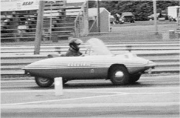
Battley's Sparrow races against Gribbeen's Escort
June 23, 2001 did not start out as a day for the record books. It had been raining all night, and by dawn there were still intermittent showers. Not good weather for a 2 hour trip, and especially bad when you are planning to be in a Drag Race. This was the day that Greg Pokorny had been dreaming of for 3 years. He is the EVent Coordinator for "The POWER of DC", the first NEDRA Drag Race on the East Coast.
I arrived at the Mason-Dixon Dragway in Hagerstown, Maryland at 10AM; there were still intermittent showers and overcast. There were a dozen hard core EV enthusiasts already there wondering what would happen to "The POWER of DC." Would it actually happen, or would we be rained out?
The track schedule called for racing to begin at 11:00 with EV-only races on the half hour till 5pm. At 11 the track officials began Tech Inspections of all race vehicles. This was a "Test and tune" day so ICErs were there as well.
At 11:30 the track officials finally announced that racing could begin. At 11:46 Bill Gingras from Annapolis, MD became the first East Coast NEDRA Racer down the track. His 36-volt home built "NO GAS" fired down the track at a blazing 48.35 mph (14.356 sec) for the 1/8 mile. Not bad for an EV built for low speed commuting in 1976. This may not have impressed the ICE observers, but it did set a NEDRA record. (First of four records, possibly five, set that day.)
In all 13 EVs raced in "The POWER of DC." "Bad Amplitude" the 336-volt Electric Rail from NetGain Technologies, came from Lockport, IL. Brian Methany came down from Bellinham, Massachusetts with his 192volt Toyota MR2. Darin Gilbert (Detroit, MI) ran his 48-volt motorcycle, and set a NEDRA record. The other racers were just slightly more local (MD, VA, PA, DC)
"Bad Amplitude" posted the fastest EV times of the day (DUH), but was only running at 40% power due to a blown controller.
Dave Mueller of E-Kart of Pennsylvania made a few runs with his Day-Glo Orange Electric Go-Kart and set a Nedra record.
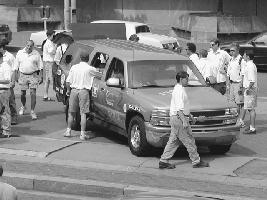
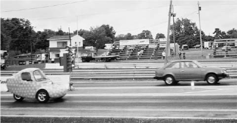
The Central that everyone (including the ICErs) thought was the "cutest thing". Devin has recently become a dealer for the Corbin Sparrow. Although he did not set any records, he did have the largest number of spectators hanging around his Sparrow (Lime Green with Mauve polka dots) in the pit area between races.
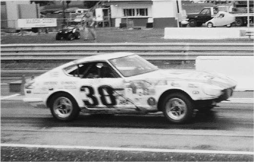
Central Shenandoah's Z-240 burns down the raceway
Shenandoah Valley Regional Governor's School showed up to show all the old fogies what a group of motivated High School Students can do to a 240-Z. Not only did they impress us, they also set a record.
Devin Battley, owner of Battley Cycles in Gaithersburg, MD, brought the EV
Chip Gribben (Laurel, MD) raced his blue 144 volt Ford Escort against the Corbin Sparrow and came in second. There were no losers at "The POWER of DC." Chip recently received an award from Montgomery County Maryland for "Environmental Commuting." He drives his EV to work every day.
There was even a featured "Battle of the Brands" between two factory-stock EVs: Charlie Garlow and his Chevy S-10 vs. Brian Murtha and his Ford Ranger. (The Chevy won). Charlie also had the most number of people drive (6) his S-10 down the track.
Bill Gingras's home-built 36Ver
By 5 o'clock, all of the attendees had had a great time; everyone had raced at least twice and some as many as 9 times. We even had a few ICErs as potential EV converts. It was time for the awards, a group photo, and then back home till next year. This EVent was sponsored by the Electric Vehicle Association of Greater Washington, D.C. (www.evadc.org).
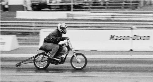
Darin Gilbert's motorcycle really shows the speed.
Details of "The POWER of DC"
97 Volts and Up Division
1st Net Gain Technologies - "Bad Amplitude" Dragster 12.046
sec.
2nd Brian Matheny - 192v Toyota MR2 18.177 sec.
3rd Bob Salem - VW pickup 18.832 sec.
4th Charlie Garlow - Factory Chevy S-10 EV 20.402 sec.
5th Chip Gribben - 144v Escort 20.737 sec.
6th Wallace Rumbarger EEI RAV-4 20.973 sec.
7th Bryan Murtha Factory Ford Ranger EV 21.016 sec.
8th Devin Battley - Corbin Sparrow 21.594 sec.
96v and Below (1/8th mile) Division
1st Dave Mueller - electric go cart 10.107 sec.
2nd Darin Gilbert - 48v motorcycle 12.086 sec.
3rd Tracey Miller - Jr. Dragster 13.33 sec.
4th Central Shenandoah Valley Regional Governors School - 240-Z 13.78
sec.
5th Bill Gingras - 36v home built EV 14.356 sec.
NEDRA records
Dave Mueller GE/I
Darin Gilbert MT/I
MT/I Bill Gingras CV/I
Central Shenandoah Valley Regional Governors School HM/G
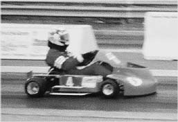
Even EV go-carts catch the thrill at the raceway
NEDRA Race Classes
SP - Street Production
MP - Modified Production
SC - Street Conversion
MC - Modified Conversion
MT - Motorcycle-Trike
DR - Dragster
GE - Go Cart
HS - High School Street
HM - High School Modified
SF - Class 64
CV - Concept Vehicle
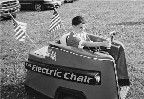
Not all EVs fit the mold...
Voltage Divisions
A - 241 V and above
B - 193V - 240V
C - 169V - 192V
D - 145V - 168V
E - 121V - 144V
F - 97V - 120V
G - 73V - 96V
H - 49V - 72V
I - 25V - 48V
J - 24V and below
NEV: A VISIT TO THE GISMO FACTORY
by Michael Everett
The Neighborhood Electric Vehicle Company was formed in 1995 to develop and produce an electric vehicle that would be environmentally friendly, fun to drive, efficient, and affordable. For NEVCO, making a difference in personal transportation involves creating an entirely new type of vehicle, a Neighborhood Electric vehicle, the Gizmo, a revolutionary concept in personal transportation. The Gizmo is a three-wheeled single-person vehicle that is designed for commuters traveling under 45 miles per trip, or 75% of all drive time.
On August 14, while in Eugene OR, I had a chance to see the Neighborhood Electric Vehicle Co. factory and offices, and meet Carl Watkins, owner/manager. He was kind enough to give my family and me a tour of the manufacturing area and let me test drive one of their production vehicles. Impressions follow:
Even a `simple' car is pretty complicated; there were jigs and paint booths and jigs and wiring layout boards and jigs everywhere, and of course lots of car parts. Looked like a pretty `together' setup, but with some room to grow as production volumes increase. He said they're doing several a month now.
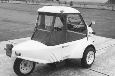
There are a whole bunch of neat design details in the vehicle. It appears well thought out. The little rubber `floor mat' that retracts so you can stand up when opening the front was just one of many examples.
It's easy to open and get into, and comfortable to sit in. Everything falls readily to hand. The controls take a moment to get used to but I was confident enough to venture out onto the street after 90 sec or so. The battery pack was mostly depleted (in the yellow zone on the gauge) but even so acceleration was more than adequate and it was up through 35 and heading for 40 before I was quite ready. Handling seemed remarkably steady even near top speed, though I didn't have much chance to try higher speed cornering.
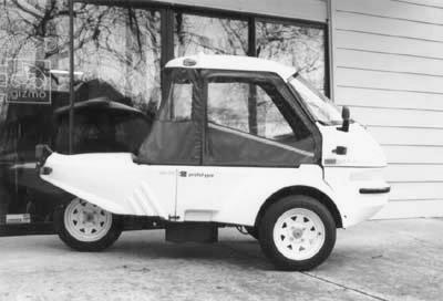
Visibility is very good and the chain noise is barely noticeable and completely masked by regular road/tire noise above 25 mph. The only thing I'd add is that I wish it had a bit faster top speed.
We quite enjoyed our time there. Thanks Carl!
To learn more about the Gizmo, visit their website at http://www.nevco.com.
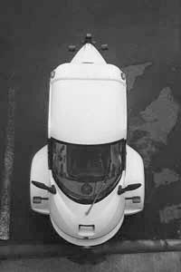
SPECS
Vehicle Weight: 340 lb.
Battery Weight: 320 - 520 lbs.
Payload: 250 - 500 lbs.
Storage Capacity: 10 cubic feet
Dimensions: 4' W x 4.5' H x 8' L
Motor: 12 HP series DC
Batteries: Deepcycle Lead Acid, 48V
Chassis: steel tube truss
Body: fiberglass
Transmission: chain drive, single speed
Brakes: hydraulic disc, hand act
Speed: up to 40 mph
Range: 45 miles std per charge
Range w/ rechg: up to 90 miles in 8 hours with recharging
Full Recharge: 8 hours
Life of Batteries: 3 to 5 years
Recharge Power: std 110V AC outlet
Price: $8650 plus shipping
Base configuration with 45 mile battery pack
By Victor Wouk
I got QUITE a charge out of Lee Hart's EXCELLENT adaptation (I would not call it a "parody") of the song THE MAN WHO NEVER RETURNED.
No apologies are needed to the Kingston Trio. Here's the scoop about the genesis of the song: IT WAS AN ELECTION CAMPAIGN SONG!The Kingston Trio did NOT originate it. They adapted the song, and gave it the wonderful delivery that we now are so familiar with.
The MTA (Metropolitan Transit Authority) of Boston was planning to raise the fare 5c from 10c, I believe. There was a complication involved difficult to explain that would
require some riders to pay the 5c AFTER they got off the train. Hence, poor Charlie, who did not have the 5c with him, would never be able to get off the train, and return home.
A candidate for some Boston elected office was AGAINST the fare increase, and commissioned this song as a radio commercial. I am having a Senior Moment, and do not remember specific dates, which won the election, etc.
To establish my bone fides as a Senior Momenter:
- The subway fare was 5c in NYC when I became sentient.
- The fare was raised to 10c around 1949.
v I remember the campaign, in 1928-9, of the NYC IRT (Interboro Rapid Transit) Company, a PRIVATELY HELD, for-profit company, that wanted to raise the fare from 5c to 7c. The Board was so sure that they would receive permission, that they minted millions of 7c tokens. Pictures of the token, and the campaign against the 7c fare, were front-page items in the NYC papers.
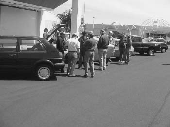 |
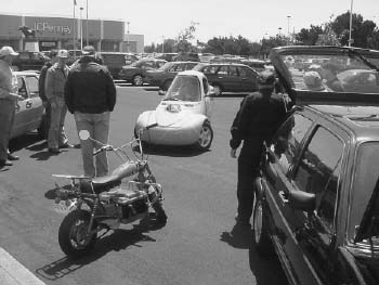 |
|
|
About 8 EVs showed up to display to the public.
|
Lots of interest, from mini-bikes to Sparrows
to VW conversions.
|
|
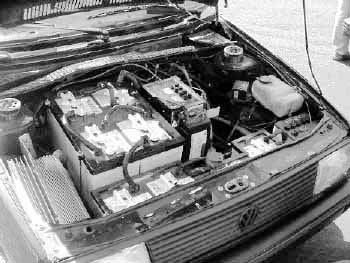 |
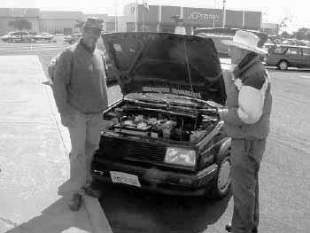 |
|
|
Excellent layout of engine (below), controller
(left), batteries and more. VW's provide great fit for all the componients.
|
Proud to drive an EV - every owner had a story
to tell.
|
|
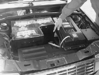 |
 |
|
|
Clean front layout, with plastic display covers
over batteries.
|
Even on-board chargers need a well-ventilated
space.
|
By Peter VanDerWal
Some who are new to EV's wonder if you construct a fan (moved by the air while the vehicle is moving) or a low amperage electric motor to turn one or more high amp. Alternators they should charge the batteries, the speed of rotation can be adjusted by different pulley ratios. On a Fiero, for instance, there is plenty of room in the front (under the hood) to do this, but shouldn't something like this work?
Ignoring matter-to-energy conversion, it takes energy to convert energy. If you are going to spin an alternator it needs mechanical energy. Part of the mechanical energy is lost in the conversion to electricity due to friction, electrical losses, etc. So to get 1 hp of electricity (746 watts) you have to put in typically 1.3 hp of mechanical energy. Now if you are going to use a motor to drive the alternator, it also has losses (just like the alternator). So in order to get 1.3 hp of mechanical energy out of the motor you have to put in something like 1.7 hp (1670 watts) of electricity into the motor.
Net result is a loss of around 1,000 watts. This idea sucks power from your batteries and gives you nothing (but a bit of extra heat) in return. And of course that doesn't take into account the losses in the belt drive system.
You don't get anything for free in this universe. In fact that's (more or less) the first law of thermodynamics. The second law of thermodynamics says you can't even break even (as shown above).
As for using the fan, it works by slowing down the air (creates drag). Your EV's main motor has to work harder to make up for the extra drag. The net result is even higher losses than above because you have more mechanical stuff (transmission, wheels, air, etc.) in-between the drive motor and the generator.
So, NO, it doesn't work. Don't feel bad, people who don't understand basic physics (and even some people who do) ask this question all the time. In fact, if you drive an EV, sooner or later someone will ask you this or a similar question.
The best you can do is to convert excess mechanical energy into electricity. Like when you need to slow down or are going down hill. Normally you would use your brakes and convert the mechanical energy into heat. Instead you can use something called regenerative, or "regen", braking; this uses your drive motor as a generator and converts some of the mechanical energy back into electricity (and slows you down).
The problem is that if you are using series wound DC motors (like most conversions do) regen is complicated and expensive, and you gain very little benefit from it except saving your brake shoes.
A Smart Electric in Georgia?
by Bob Oldham
A Georgia man whose companies build some very fast race cars has begun a venture to bring small electric cars to Georgia in a big way. Donald Panoz of Braselton, Georgia is working to reach agreement with DaimlerChrysler to convert the German-American car-maker's smart® cars to all-electric drive for use as "station cars" linking public transit to destinations in the traffic-clogged Atlanta metropolitan area.
Panoz has established a new company, eMotion Mobility, to import and convert as many as 5000 smart gliders a year, installing the electric drive train in them in a plant to be located somewhere in south Georgia or north Florida. At the projected production volume, eMotion Mobility would be the largest electric vehicle producer ever in the United States. The smart is a tiny 2-seater 5 feet shorter than the new VW Beetle and is becoming popular in the crowded cities of Europe.
One hundred years after the first production electric cars came on the
market, there are still only about 28,000 electric or hybrid vehicles
in the United States. In contrast, Ford sells more of its popular Explorer
SUVs than that every month. The prospect for an increase in the EV numbers
is generating excitement in the EV community.
"I think that this is one of the brightest, most promising EVentures that I have seen in some time," says Dave Goldstein, president of EVA/DC and a consultant to EV manufacturers. "In many ways it reminds me of the groundbreaking Tropica venture which showed the potential for a small manufacturer to assemble an affordable, high-value, sporty two-seater EV." Goldstein continues, "But, whereas Tropica was perpetually undercapitalized, and failed because of it, this project has been far better organized with some brilliant embellishments, including the support of one of the world's leading auto manufacturers and the use of a glider vehicle that has already proven itself in Europe. And that could make all the difference this time around."
Used as "station cars", the electric smarts would be parked at transit stops, shopping malls, campuses, and employment centers, and would be available for use by multiple drivers on a rotating basis by subscription. (Subscription costs have not yet been determined.) They would be reserved online, and drivers would use a computer "smart card" to gain access for operation. Usage and location would be tracked by GPS.
The range of 60 to 70 miles and the top speed of 70mph that are projected for the electric smarts, plus air-conditioning for the Georgia climate, would make these economical and clean vehicles an attractive alternative to Atlanta's presently jammed and smoggy roads. Two similar "shared electric vehicle" projects, at Emory University and the Georgia Power offices, together using about 24 vehicles, were recently announced.
John Wilson, president of eMotion, predicts that the first smart electrics will be on the streets by the end of 2002.
Panoz Motor Sports began experimenting with hybrid race cars in 1998, and Panoz contacted the Southern Coalition for Advanced Transportation last year and asked the Coalition to develop a plan to use EVs in Atlanta city traffic. If the scheme is successful in Atlanta Panoz hopes to take the e-car system to other Southern cities that have transportation and urban pollution problems, and beyond that to the rest of the country.
[For EVs for Sale, see http://eaaev.org ]